SVG Rasterizer
Overview
In this project, you will implement a simple software rasterizer that draws points, lines, triangles, and bitmap images. When you are done, you will have a viewer that supports the basic features of the Scalable Vector Graphics (SVG) format that is now widely used on the internet.
Getting started
We will be distributing assignments with git. You can find the repository for this assignment at https://github.com/CMU-Graphics/DrawSVG. If you are unfamiliar with git, here is what you need to do to get the starter code:
$ git clone https://github.com/CMU-Graphics/DrawSVG.git
This will create a folder with all the source files.
Build Instructions
In order to ease the process of running on different platforms, we will be using CMake for our assignments. You will need a CMake installation of version 2.8+ to build the code for this assignment. It should also be relatively easy to build the assignment and work locally on Windows, OSX or 64-bit version of Linux. Building on ARM (e.g. Raspberry Pi, some Chromebooks) is currently not supported.
VSCode Build Instructions (All Platforms)
We recommend using Visual Studio Code on all platforms. Once you install CMake and VSCode, you will also need to install the C/C++ extension within VSCode.
The build and launch data is contained within the .vscode directory. Select the folder for your compiler and move launch.json and tasks.json up one level into the .vscode directory. To set commandline arguments, go to launch.json and add them within args. For example, to run the program with test 1, you would add ./basic/test1.svg. You can build using Ctrl+Shift+B and debug using F5. If you feel that your program is running slowly, you can also change the build mode to Release from Debug.
Commonly used Hotkeys:
-
Ctrl+Shift+B - Build
-
F5 - Debug
- F9 - Toggle Breakpoint
- F10 - Step Over
- F11 - Step Into
- Shift+F5 - Stop
-
Ctrl+P - Search for file
-
Ctrl+Shift+P - Run Command
-
Right click to go to definition/declaration/references
OS X/Linux Build Instructions
If you are working on OS X and do not have CMake installed, we recommend installing it through Homebrew: $ brew install cmake. You may also need the freetype package $ brew install freetype.
If you are working on Linux, you should be able to install dependencies with your system's package manager as needed (you may need cmake and freetype, and possibly others).
To build your code for this assignment:
$ cd DrawSVG && mkdir build && cd build
$ cmake ..
$ make
These steps (1) create an out-of-source build directory, (2) configure the project using CMake, and (3) compile the project. If all goes well, you should see an executable drawsvg in the build directory. As you work, simply typing make in the build directory will recompile the project.
Windows Build Instructions using Visual Studio
We have a beta build support for Windows systems. You need to install the latest version of CMake and install Visual Studio Community. After installing these programs, you can run runcmake_win.bat by double-clicking on it. This should create a build directory with a Visual Studio solution file in it named drawsvg.sln. You can double-click this file to open the solution in Visual Studio.
If you plan on using Visual Studio to debug your program, you can change drawsvg project in the Solution Explorer as the startup project by right-clicking on it and selecting Set as StartUp Project. You can also set the commandline arguments to the project by right-clicking drawsvg project again, selecting Properties, going into the Debugging tab, and setting the value in Command Arguments. If you want to run the program with the basic svg folder, you can set this command argument to ../../svg/basic. After setting all these, you can hit F5 to build your program and run it with the debugger.
If you feel that your program is running slowly, you can also change the build mode to Release from Debug by clicking the Solution Configurations drop down menu on the top menu bar. Note that you will have to set Command Arguments again if you change the build mode.
Windows Build Instructions Using CLion
(tested on CLion 2018.3)
Open CLion, then do File -> Import Project..
In the popped out window, find and select the project folder ...\DrawSVG, click OK, click Open Existing Project, then select New Window
Make sure the drop down menu on top right has drawsvg selected (it should say drawsvg | Debug). Then open the drop down menu again and go to Edit Configurations..
Fill in Program arguments, say, ./svg/basic, then click Apply and close the popup
Now you should be able to click on the green run button on top right to run the project.
Using the Mini-SVG Viewer App
When you have successfully built your code, you will get an executable named drawsvg. The drawsvg executable takes exactly one argument from the command line. You may load a single SVG file by specifying its path. For example, to load the example file svg/basic/test1.svg :
./drawsvg ../svg/basic/test1.svg
When you first run the application, you will see a picture of a flower made of a bunch of blue points. The starter code that you must modify is drawing these points. Now press the R key to toggle display to the staff's reference solution to this assignment. You'll see that the reference differs from "your solution" in that it has a black rectangle around the flower. (This is because you haven't implemented line drawing yet!)
While looking at the reference solution, hold down your primary mouse button (left button) and drag the cursor to pan the view. You can also use scroll wheel to zoom the view. (You can always hit SPACE to reset the viewport to the default view conditions). You can also compare the output of your implementation with that of the reference implementation. To toggle the diff view, press D. We have also provided you with a "pixel-inspector" view to examine pixel-level details of the currently displayed implementation more clearly. The pixel inspector is toggled with the Z key.
For convenience, drawsvg can also accept a path to a directory that contains multiple SVG files. To load files from svg/basic:
./drawsvg ../svg/basic
The application will load up to nine files from that path and each file will be loaded into a tab. You can switch to a specific tab using keys 1 through 9.
Summary of Viewer Controls
A table of all the keyboard controls in the draw application is provided below.
| Command | Key |
|---|---|
| Go to tab | 1 ~ 9 |
| Switch to hw renderer | H |
| Switch to sw renderer | S |
| Toggle sw renderer impl (student soln/ref soln) | R |
| Regenerate mipmaps for current tab (student soln) | ; |
| Regenerate mipmaps for current tab (ref soln) | ' |
| Increase samples per pixel | = |
| Decrease samples per pixel | - |
| Toggle text overlay | ` |
| Toggle pixel inspector view | Z |
| Toggle image diff view | D |
| Reset viewport to default position | SPACE |
Other controls:
-
Panning the view: click and drag the cursor
-
Zooming in and out: scroll wheel (typically a two-finger drag on a trackpad)
What You Need to Do
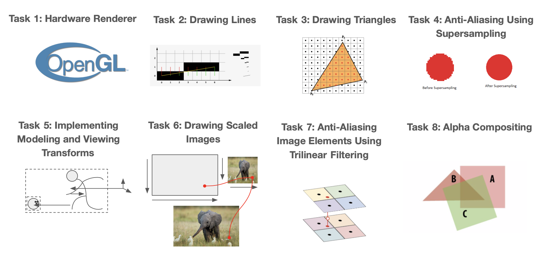
The assignment is divided into nine major tasks, which are described below in the order the course staff suggests you attempt them. You are of course allowed to do the assignment in any order you choose. Although you have a little over 2 weeks to complete this assignment, the assignment involves significant implementation effort. Also, be advised that meeting the requirements of later tasks may involve restructuring code that you implemented in earlier ones. We have split the assignment into a checkpoint and final submission to ensure you do not fall behind. Please consult the schedule on the course webpage for checkpoint and final due dates. Checkpoint for this assignment entails fully implementing tasks 1-4, and the final entails fully implementing tasks 5-8. All extra credit code you write for tasks 1-8 will be graded along with final, so don't worry too much about trying to get them done for the checkpoint, and instead focus more on completing the tasks themselves :)
Grading
DrawSVG is made by humans, and will be graded by humans. We are not asking for a pixel-perfect recreation of the reference solution. Floating-point arithmetic on different architectures may lead to subtle inconsistencies that may make your solution a few pixels different than the reference. You should instead aim to have the bigger picture down: lines are in the general same area and thickness, no gaps in triangle fills, etc. It should be clear that if we held the two images together side by side, there shouldn't be a difference to the human eye (we're looking for eye-level differences, not pixel level differences). If you are unsure about grading, feel free to ask on piazza.
Please make sure that your submission builds when submitting to Autolab. Check the assignment details on the course website for instructions on how to tar your files. We will run an autograding script to make sure you've included all the necessary filles and to ensure your program complies on the Gates 5 machines. If you receive a negative score, Autolab will provide you feedback on what you need to fix in your program before submitting. You have unlimited submissions.
Friendly Advice from your TAs
-
As always, start early. There is a lot to implement in this assignment, so don't fall behind!
-
Open
.../DrawSVG/CMU462/docs/html/index.htmlwith a browser to see documentation of many utility classes, especially the ones related to vectors and matrices. -
Be careful with memory allocation, as too many or too frequent heap allocations will severely degrade performance.
-
Be careful with types (e.g. float, double, int, uint8_t), casting, and using the right functions for each type. Take note of the
uint8_to_floatandfloat_to_uint8functions intexture.cpp, which you may find helpful for later tasks. -
While C has many pitfalls, C++ introduces even more wonderful ways to shoot yourself in the foot. Later assignments will require you to use C++ classes and objects, so take the time to learn the new features C++ introduces.
-
Currently, DrawSVG does not support rendering
<circle>svg elements (which is different from<ellipse>).
Getting Acquainted with the Starter Code
Before you start, here are some basic information on the structure of the starter code.
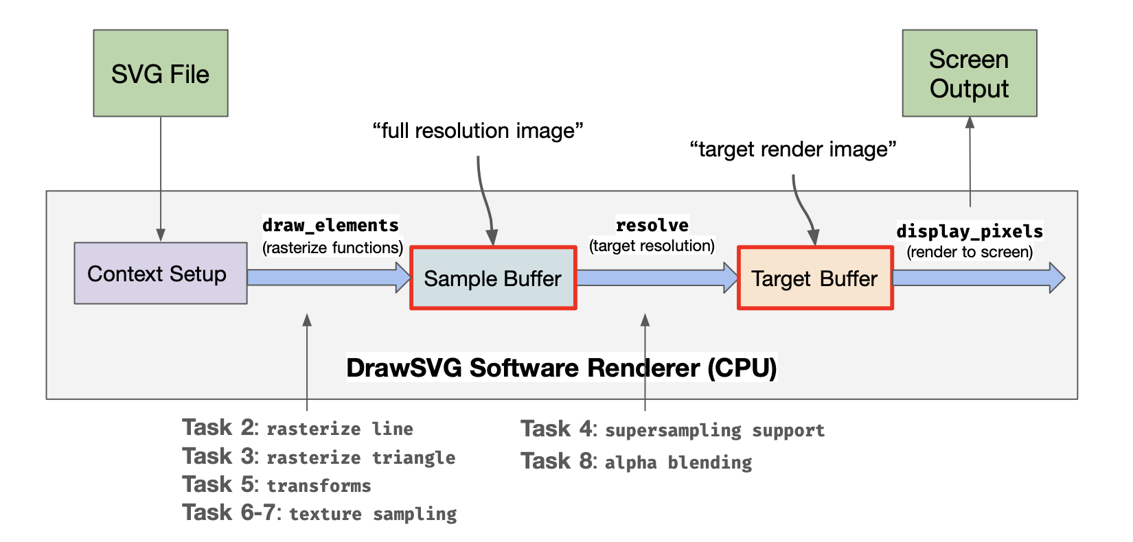
The program reads in an SVG and initiates the window via context setup. The SVG is then parsed into a set of primitives, and the draw_elements function is called on each SVG element, rasterizing the primitives to pixels in the sample buffer. Pixels in the sample buffer are then filtered in the resolve function and sent to the target buffer where they are displayed onscreen. The above diagram illustrates how each task falls into the pipeline. The sample buffer takes multiple samples per pixel, and adjacent pixels in the sample buffer are averaged together for each target buffer pixel.
All the source code files are contained in src directory. You're welcome to browse through and/or edit any file, but the following ones and their headers are probably the most relevant:
-
hardware/hardware_renderer(task 1) -
software_renderer(most tasks) -
viewport(task 5) -
texture(tasks 6, 7)
Most of your work will be constrained to implementing part of the class SoftwareRendererImp in software_renderer.cpp. The SoftwareRendererImp class is derived from the SoftwareRenderer and SoftwareRendererRef classes. Please do not modify SoftwareRenderer or SoftwareRendererRef or else your program will crash. The most important method is draw_svg which (not surprisingly) accepts an SVG object to draw. An SVG file defines its canvas (which defines a 2D coordinate space), and specifies a list of shape elements (such as points, lines, triangles, and images) that should be drawn on that canvas. Each shape element has a number of style parameters (e.g., color) as well as a modeling transform used to determine the element's position on the canvas. You can find the definition of the SVG class (and all the associated SVGElements) in svg.h. Notice that one type of SVGElement is a group that itself contains child elements. Therefore, you should think of an SVG file as defining a tree of shape elements. (Interior nodes of the tree are groups, and leaves are shapes.)
Another important method on the SoftwareRendererImp class is set_render_target(), which provides your code a buffer corresponding to the output image (it also provides width and height of the buffer in pixels, which are stored locally as target_w and target_h). This buffer is often called the "render target" in many applications, since it is the "target" of rendering commands. We use the term pixel here on purpose because the values in this buffer are the values that will be displayed on screen. Pixel values are stored in row-major format, and each pixel is an 8-bit RGBA value (32 bits in total). Your implementation needs to fill in the contents of this buffer when it is asked to draw an SVG file.
set_render_target() is called whenever the user resizes the application window.
A Simple Example: Drawing Points
You are given starter code that already implements drawing of 2D points. To see how this works, begin by taking a look at draw_svg() in software_renderer.cpp. The method accepts an SVG file, and draws all elements in the SVG file via a sequence of calls to draw_element(). For each element draw_element() inspects the type of the element, and then calls the appropriate draw function. In the case of points, that function is draw_point().
The position of each point is defined in a local coordinate frame, so draw_point() first transforms the input point into its screen-space position (see line Vector2D p = transform(point.position)). This transform is set at the beginning of draw_svg(). In the starter code, this transform converts from the svg canvas' coordinate system to screen coordinates. You will need to handle more complex transforms to support more complex SVG files and implement mouse viewing controls later in the assignment.
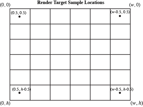
The function rasterize_point() is responsible for actually drawing the point. In this assignment we define screen space for an output image of size (target_w, target_h) as follows:
-
(0, 0)corresponds to the top-left of the output image -
(target_w, target_h)corresponds to the bottom-right of the output image -
Please assume that screen sample positions are located at half-integer coordinates in screen space. That is, the top-left sample point is at coordinate (0.5, 0.5), and the bottom-right sample point is at coordinate (target_w-0.5, target_h-0.5).
To rasterize points, we adopt the following rule: a point covers at most one screen sample: the closest sample to the point in screen space. This is implemented as follows, assuming (x, y) is the screen-space location of a point.
int sx = (int) floor(x);
int sy = (int) floor(y);
Of course, the code should not attempt to modify the render target buffer at invalid pixel locations.
if ( sx < 0 || sx > target_w ) return;
if ( sy < 0 || sy > target_h ) return;
If the points happen to be on screen, we fill in the pixel with the RGBA color associated with the point.
  render_target[4 * (sx + sy * target_w)    ] = (uint8_t) (color.r * 255);
  render_target[4 * (sx + sy * target_w) + 1] = (uint8_t) (color.g * 255);
  render_target[4 * (sx + sy * target_w) + 2] = (uint8_t) (color.b * 255);
  render_target[4 * (sx + sy * target_w) + 3] = (uint8_t) (color.a * 255);
At this time the starter code does not correctly handle transparent points. We'll come back to this later.
Now that you understand the basics of drawing elements, let's get to work actually drawing more interesting elements than points!
Task 1: Hardware Renderer
In this task, you will finish implementing parts of the hardware renderer using OpenGL. In particular, you will be responsible for implementing rasterize_point(), rasterize_line(), and rasterize_triangle() in hardware/hardware_renderer.cpp. All other OpenGL context has been set up for you outside of these methods, so you only need to use glBegin(), glEnd(), and appropriate function calls in between those two functions. (You may be interested in glColor4f() and glVertex2f(), along with GL_POINTS, GL_LINES, and GL_TRIANGLES.) You can find an extensive guide to OpenGL here, but feel free to google function names for quick documentation.
Once you're done, you can test your solution by running DrawSVG and pressing h. Your hardware renderer should now be able to correctly render all tests in basic/ and alpha/, and implementing the remaining tasks will add functionality to your software renderer. Remember to compare your render results with the reference, and make sure there are no major visual differences.
Task 2 : Warm Up: Drawing Lines
In this task you will add line drawing functionality by implementing the function rasterize_line() in software_renderer.cpp.
In Lecture 1, we discussed a few ways to think about rasterizing a line. (Recall we talked about possible rules for what samples are considered to be "covered" by the line, and we discussed algorithms for efficiently determining what samples meet that criteria. Since line drawing is very well documented on the web (and this is just a warm up exercise), you may consult the web and use any algorithm you wish. However, your solution should:
-
Handle non-integer vertex coordinates passed to
rasterize_line(). -
Handle lines of any slope.
-
Perform work proportional to the length of the line (methods that perform work for every pixel on screen or for all samples in the bounding box of the line are not acceptable solutions).
We encourage you to start with an implementation of Bresenham's algorithm and then, if you wish, continue on with implementations that improve quality (e.g., draw smooth lines) or optimize drawing performance.
When you are done, your solution should be able to correctly render basic/test2.svg.
Possible Extra Credit Extensions:
-
(2 pts) If you compare your initial Bresenham results with the reference implementation, you will notice that the reference solution generates smooth lines. For example, you could modify your Bresenham implementation to perform Xiaolin Wu's line algorithm.
-
(2 pts) Add support for specifying a line width.
Task 3: Drawing Triangles
In this task, you will implement rasterize_triangle() in software_renderer.cpp.
Your implementation should:
-
Sample triangle coverage using the methods discussed in Lecture Drawing a Triangle. While in Task 2 you were given choice in how you defined the outputs of line drawing, there is an exact solution to the problem of sampling triangle coverage. The position of screen sample points--at half-integer coordinates in screen space--was described above.
-
To receive full credit in Task 3 your implementation should assume that a sample point on a triangle edge is covered by the triangle. Your implementation DOES NOT need to respect the triangle "edge rules" to avoid "double counting" as discussed in class. (but we encourage you to try!)
-
Your implementation should use an algorithm that is more work efficient than simply testing all samples on screen. To receive full credit it should at least constrain coverage tests to samples that lie within a screen-space bounding box of the triangle. However, we encourage exploration of even more efficient implementations, such as ones that employ "early out" optimizations discussed in lecture.
-
When a triangle covers a sample, you should write the triangle's color to the location corresponding to this sample in
render_target.
Once you have successfully implemented triangle drawing, you will able to draw a large number of examples. When loading an SVG, the provided code triangulates convex polyhedra into a list of triangles for you, so by implementing support for rasterizing triangles, the viewer now supports drawing any of these shapes as well. (When parsing the SVG, we convert rectangles and polygons specified in the file into lists of triangles.)
When you are done, you should be able to draw basic/test3.svg, basic/test4.svg, and basic/test5.svg.
Note that the vertices may be in counter-clockwise or clockwise order when passed in. Using the cross-product to check orientation may be helpful.
Task 4: Anti-Aliasing Using Supersampling
This part of the assignment requires only knowledge of concepts from Lectures Course Introduction and Drawing a Triangle.
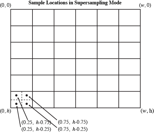
In this task, you will extend your rasterizer to anti-alias triangle edges via supersampling. In response to the user changing the screen sampling rate (the = and - keys), the application will call set_sample_rate() . The parameter sample_rate defines the sampling rate in each dimension, so a value of 2 would correspond to a sample density of 4 samples per pixel. In this case, the samples lying within the top-left pixel of the screen would be located at locations (0.25, 0.25), (0.75, 0.25), (0.25, 0.75), and (0.75, 0.75).
It's reasonable to think of supersampled rendering as rendering an image that is sample_rate times larger than the actual output image in each dimension, then resampling the larger rendered output down to the screen sampling rate after rendering is complete. Note: If you implemented your triangle rasterizer in terms of sampling coverage in screen-space coordinates (and not in terms of pixels), then the code changes to support supersampling should be fairly simple for triangles.
To help you out, here is a sketch of an implementation:
-
The image being rendered is stored in
render_target, an array that stores each pixel's color components as anuint8_tin rgbargba... order. The width and height in pixels of therender_targetare stored astarget_wandtarget_hrespectively. Refer torasterize_pointto see how it can be modified. -
When rasterizing primitives such as triangles, rather than directly updating
render_target, your rasterization should update the contents of a larger buffer (perhaps call itsample_bufferorsupersample_target) that holds the per-super-sample results. It's up to you to manage this buffer yourself. (Hint: Seesoftware_renderer.hfor declarations of helpers used by the reference. The functionsvector::resize()andmemset()may be worth looking into.)- Don't add your sample buffer as a member of
SoftwareRenderer: instead add it toSoftwareRendererImp. This is because the pre-compiled reference code relies on the current memory layout ofSoftwareRenderer.
- Don't add your sample buffer as a member of
-
After rendering is complete, your implementation must resample the supersampled results buffer to obtain sample values for the render target. This is often called "resolving" the supersample buffer into the render target. Please implement resampling using a simple unit-area box filter.
-
Note that the function
SoftwareRendererImp::resolve()is called bydraw_svg()after the SVG file has been drawn. Thus it's a very convenient place to perform resampling.
When you are done, try increasing the supersampling rate in the viewer, and bask in the glory of having much smoother triangle edges.
Also observe that after enabling supersampled rendering, something might have gone very wrong with the rasterization of points and lines. (Hint: they probably appear to get thinner!) Please modify your implementation of rasterizing points and lines so that supersampled rendering of these primitives preserves their thickness across different supersampling rates. Consider having separate functions for filling a "pixel" and filling a "sample." (A solution that does not anti-alias points and lines is acceptable.)
Possible Extra Credit Extensions:
-
(3 pts) Implement Morphological anti-aliasing (MLAA), rather than supersampling. It's shocking how well this works. MLAA is a technique used throughout the gaming community to avoid the high cost of supersampling but still avoid objectionable image artifacts caused by aliasing. (A more advanced version of MLAA is here).
-
(1 pts) Implement jittered sampling to improve image quality when supersampling.
-
(2 pts) Implement higher quality resampling filters than a box and analyze their impact on image quality.
Task 5: Implementing Modeling and Viewing Transforms
Part 1: Modeling Transforms
This part of the assignment assumes knowledge of concepts in Lecture Transformations.
In previous lectures we discussed how it is common (and often very useful) to describe objects and shapes in their own local coordinate spaces and then build up more complicated objects by positioning many individual components in a single coordinate space. In this task you will extend the renderer to properly interpret the hierarchy of modeling transforms expressed in SVG files.
Recall that an SVG object consists of a hierarchy of shape elements. Each element in an SVG is associated with a modeling transform (see SVGElement.transform in svg.h) that defines the relationship between the object's local coordinate space and the parent element's coordinate space. At present, the implementation of draw_element()ignores these modeling transforms, so the only SVG objects your renderer has been able to correctly draw were objects that contained only identity modeling transforms.
Please modify draw_svg() and draw_element() to implement the hierarchy of transforms specified in the SVG object. (You can do this in no more than a few lines of code.) You're also free to add code to software_renderer.h, though minimal changes should be necessary for this task.
When you are done, you should be able to draw basic/test6.svg.
Hint: If there is an SVGElement which is not in a group, the modeling transform should be the relationship between its local coordinate space and the canvas space. If it is in a group, the modeling transform should be the relationship between its local coordinate space and its parent element's local coordinate space. Look at how the transformation matrix in software renderer is applied, and think about how you can modify this to take into account each SVGElement's transform.
Part 2: Viewing Transform
Notice the staff reference solution supports image pan and zoom behavior (drag the mouse to pan, use the scroll wheel to zoom). To implement this functionality in your solution, you will need to implement ViewportImp::set_viewbox() in viewport.cpp.
A viewport defines a region of the SVG canvas that is visible in the app. The 3 properties we care about here are centerX, centerY and vspan (vertical span). They are all defined in svg coordinate space.
When the application initially launches, the entire canvas is in view. For example, if the SVG canvas is of size 400x300, then the viewport will initially be centered on the canvas, and have a vertical field of view that spans the entire canvas. Specifically, the member values of the Viewport class will look like: centerX=200, centerY=150, and vspan is some number>=150.
When user actions require the viewport be changed, the application will call update_viewbox() with the appropriate parameters. Given this change in view parameters, you should implement set_viewbox() to compute and set transform svg_2_norm (by calling set_svg_2_norm) based on the new view parameters. This transform, which involves translation and scaling, should map the SVG canvas coordinate space to a normalized device coordinate space where the top left of the visible SVG coordinate maps to (0, 0) and the bottom right maps to (1, 1). For example, for the values centerX=200, centerY=150, vspan=10, then SVG canvas coordinate (200, 150) transforms to normalized coordinate (0.5, 0.5) (center of screen) and canvas coordinate (200, 160) transforms to (0.5, 1) (bottom center).
Once you have correctly implemented set_viewbox(), your solution will respond to mouse pan and zoom in the same way as the reference implementation.
Task 6: Drawing Scaled Images
This part of the assignment requires knowledge of concepts in Lecture Perspective Projection and Texture Mapping.
In this task, you will implement rasterize_image() in software_renderer.cpp.
To keep things very simple, we are going to constrain this problem to rasterizing image elements that are positioned on the SVG canvas via translations and scaling, but not rotations. Therefore, rasterize_image() should render the specified image into an axis-aligned rectangle on screen whose top-left coordinate is (x0, y0) and whose bottom-right coordinate is (x1, y1). Your implementation should adhere to the following specification:
-
The image element should cover all screen samples inside the specified rectangle.
-
For each image, texture space spans a [0-1]^2 domain as described in class. That is, given the example above, the mapping from screen-space to texture-space is as follows:
(x0, y0)in screen space maps to image texture coordinate(0, 0)and(x1, y1)maps to(1, 1). -
You may wish to look at the implementation of input texture images in
texture.h/.cpp. The classSampler2Dprovides skeleton of methods for nearest-neighbor (sample_nearest()), bilinear (sample_bilinear()), and trilinear filtering (sample_trilinear()). There is a pre-existing instance of Sampler2D,sampler, insoftware_renderer.h. -
In this task, for each covered sample, the color of the image at the specified sample location should be computed using bilinear filtering of the input texture. Therefore you should implement
Sampler2D::sample_bilinear()intexture.cppand call it fromrasterize_image(). (However, we recommend first implementingSampler2D::sample_nearest()-- as nearest neighbor filtering is simpler and will be given partial credit.) -
As discussed in class, please assume that image pixels correspond to samples at half-integer coordinates in texture space.
-
The
Texturestruct stored in theSampler2Dclass maintains multiple image buffers corresponding to a mipmap hierarchy. In this task, you will sample from level 0 of the hierarchy:Texture::mipmap[0]. In other words, if you call one of the samplers above, you should pass in0for the level parameter.
When you are done, you should be able to draw basic/test7.svg.
Task 7: Anti-Aliasing Image Elements Using Trilinear Filtering
This part of the assignment requires knowledge of concepts in Lecture Perspective Projection and Texture Mapping.
In this task you will improve your anti-aliasing of image elements by adding trilinear filtering. This will involve generating mipmaps for image elements at SVG load time and then modifying your sampling code from Task 6 to implement trilinear filtering using the mipmap. Your implementation is only required to work for images that have power-of-two dimensions in each direction.
-
To generate mipmaps, you need to modify code in
Sampler2DImp::generate_mips()intexture.cpp. Code for allocating all the appropriate buffers for each level of the mipmap hierarchy is given to you. However, you will need to populate the contents of these buffers from the original texture data in level 0. Your implementation can assume that all input texture images have power of two dimensions. (But it should not assume inputs images are square.) -
Then modify your implementation of
rasterize_image()from Task 6 to perform trilinear filtered sampling from the mipmap. Your implementation will first need to compute the appropriate level at which to sample from the mip-hierarchy. Recall from class that as image elements shrink on screen, to avoid aliasing the rasterizer should sample from increasingly high (increasing prefiltered) levels of the hierarchy. -
The method
Sampler2D::sample_trilinear()has two parameters,u_scaleandv_scale, which depend on the sample rate and the size of the image. It is up to you how to use them.
The program only stores a single set of mipmaps for each image, so the rasterize_image() routine (both your implementation and the reference solution) will use whichever mipmaps have been generated most recently using the ' and ; keys. Be sure you are testing with your own mipmaps and not the reference ones.
At this point, zooming in and out of your image should produce nicely filtered results! To test this functionality, try zooming out on basic/test7.svg.
Task 8: Alpha Compositing
Up until this point your renderer was not able to properly draw semi-transparent elements. Therefore, your last programming task in this assignment is to modify your code to implement Simple Alpha Blending in the SVG specification.
Note that in the above link, all the element and canvas color values assume premultiplied alpha. Refer to lecture Depth and Transparency and this blog post for the differences between premultiplied alpha and non-premultiplied alpha.
While the application will always clear the render target buffer to the canvas color at the beginning of a frame to opaque white ((255,255,255,255) in RGBA) before drawing any SVG element, your transparency implementation should make no assumptions about the state of the target at the beginning of a frame.
You will need to modify the parts of the code which write to the supersample buffer.
When you are done, you should be able to correctly draw the tests in /alpha.
Task 9: Draw Something!!!
Now that you have implemented a few basic features of the SVG format, it is time to get creative and draw something!
You can create an SVG file in popular design tools like Adobe Illustrator or Inkscape and export SVG files, or use a variety of editors online. Since an SVG file is just an XML file, you could even use a text editor or write a script to generate the text!
Be aware that our starter code and your renderer implementation only support a subset of the features defined in the SVG specification, and applications like Adobe Illustrator or Inkscape may not always encode shapes with the primitives we support. (You may need to convert complicated paths to the basic primitives in these tools. This Path to Polygon Converter might be of use.)
If you're using InkScape, and you save your drawing in InkScape as an InkScape svg or Plain svg, the entire drawing will appear black in DrawSVG.
To work around this, you should instead save it as an Optimized SVG. In the resulting dialog, be sure to select Convert CSS attributes to XML attributes, and deselect Shorten color values.
If you're using Illustrator, and you get errors with opening your generated SVG file in DrawSVG, make sure your <svg> tag contains a width and height field, with set values. Look at the test case SVGs in the svg/ folder for reference.
Please name this file task9.svg.
Going Further: Tasks that May Potentially Win You Extra Credit:
Implement More Advanced Shapes
We have provided you with a couple of examples of subdividing complex, smooth complex shapes into much simpler triangles in /subdiv. Subdivision is something you will dig into in great detail in the next assignment. You can see subdivision in action as you step though the test files we provided.
In addition to what you have implemented already, the SVG Basic Shapes also include circles and ellipses. We may support these features by converting them to triangulated polygons. But if we zoom in on the edges, there will be a point at which the approximation breaks down and the image no longer will look like a smooth curve. Triangulating more finely can be costly as a large number of triangles may be necessary to get a good approximation. Is there a better way to sample these shapes? For example, implement draw_ellipse in software_renderer.cpp and hardware/hardware_renderer.cpp (2 pts).
Resources and Notes
Table of Content